
The horn guides radio waves toward the copper probe inside the can. Follow these steps for the standard 2021 design. The can and antenna page adds detailed soldering instructions and videos.
On this page: Materials, panel dimensions, cutting layout, joining panels, and attaching the can.
Build a horn from foil-faced insulation board and attach it to a metal can receiver. A separate cradle supports the assembly and lets you adjust its elevation.
Materials
| Part | Specification |
|---|---|
| Insulation board | 4 × 8-foot sheet of foil-faced insulation board |
| Metal can | New, empty 1-gallon F-style metal container |
| Copper probe | 4- or 6-gauge copper wire, 5.25 cm long |
| Connector | Four-hole, panel-mount male bulkhead SMA feedthrough |
| Aluminum flashing | Two pieces, each 2 × 6 inches |
| Tape | Aluminum foil tape and duct tape |
One insulation sheet makes one horn; two sheets can make three horns. Foil tape covers the interior seams and protects the exposed edges.
Use a new, empty can. Do not cut, drill, or heat a container that held flammable liquid.
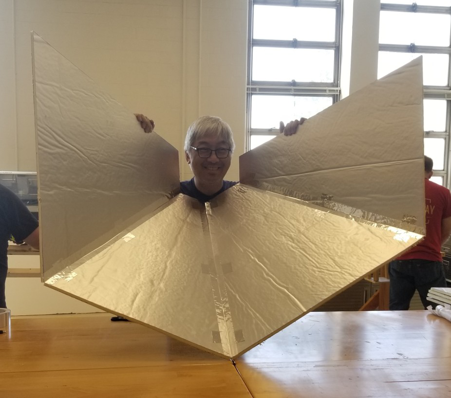
Figure 1. An assembled foil-faced horn.
Cut the horn panels
Cut two large panels and two small panels from foil-faced insulation board. Their short edges form the opening around the can.
| Panel | Quantity | Wide edge | Short edge | Height |
|---|---|---|---|---|
| Large | 2 | 29 5/8 in | 6 5/8 in | 28 3/4 in |
| Small | 2 | 24 in | 4 1/8 in | 29 3/8 in |
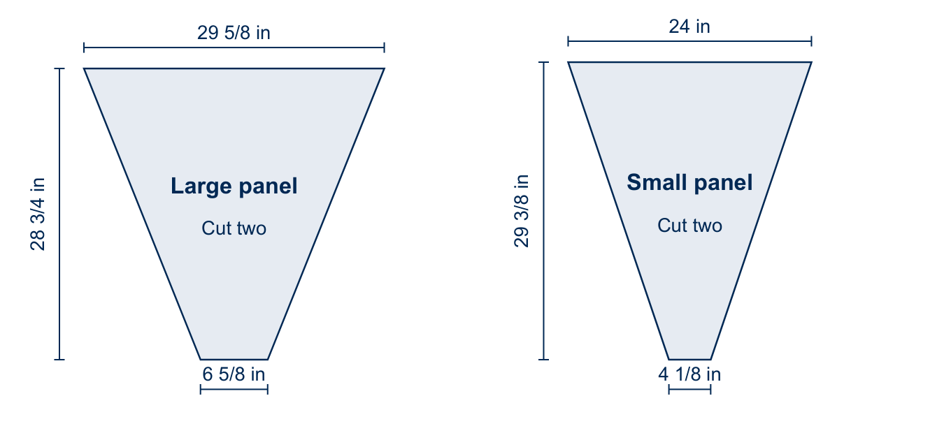
Figure 2. Dimensions of the two panel shapes. Heights are perpendicular to the parallel edges.
Plan the cuts
- Have the hardware store cut the sheet into three 32-inch strips for easier transport, if needed.
- Use the cutting layout below. Cut the two large panels together, then the two small panels.
- Measure every position from the same side of the sheet. The layout uses the left edge.
- Check the short edges carefully. These edges must fit the can opening.
- Keep the remaining strip for spare panels. Fitting one large and one small panel together takes more care.
Each large panel narrows by 11 1/2 inches on each side. Each small panel narrows by 9 15/16 inches.
Arrange the panels on the sheet
The first two strips supply one horn. The third strip can supply a spare large panel and a spare small panel.
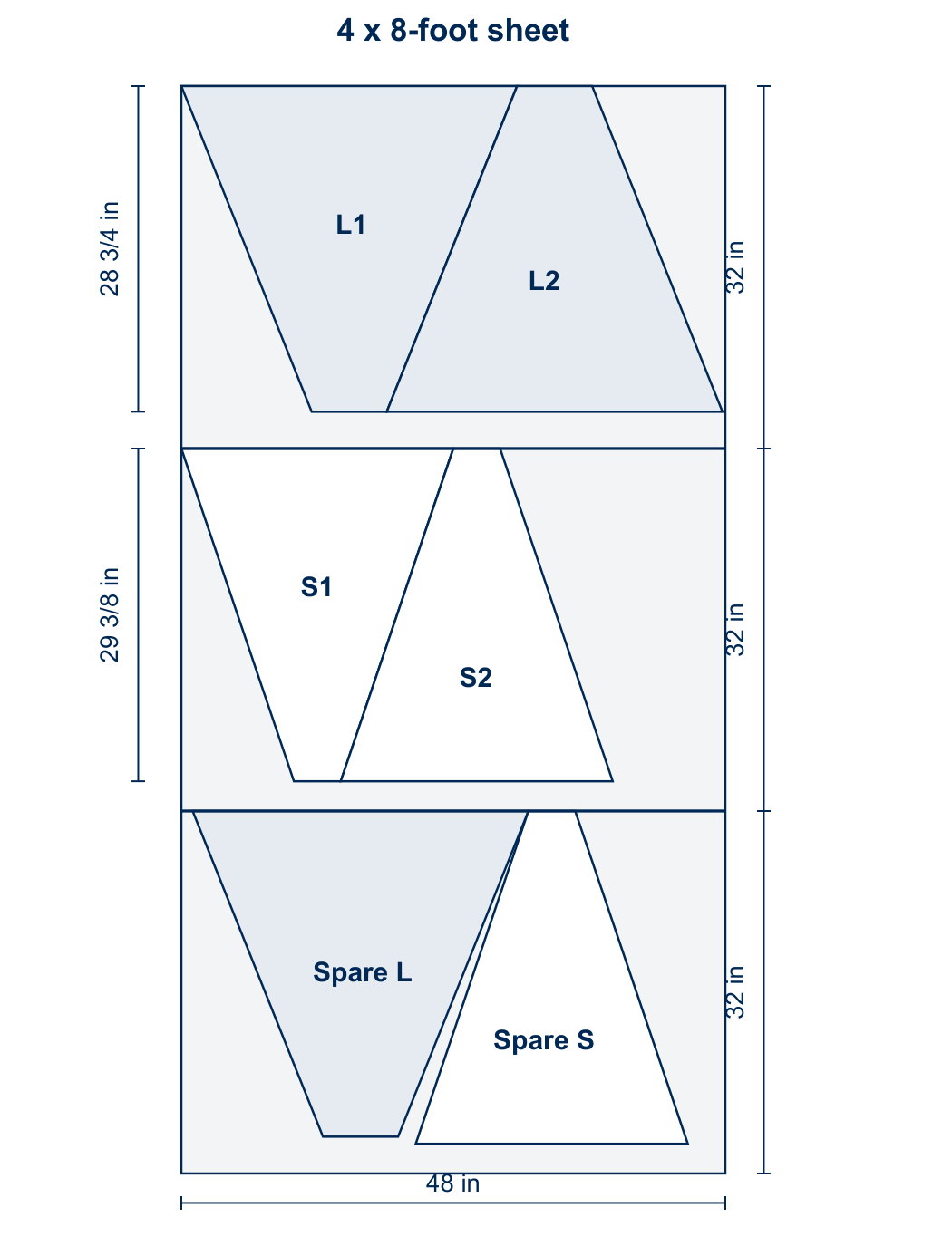
Figure 3. L marks large panels; S marks small panels. Unlabeled areas are scrap.
The upper pair leaves 1/4 inch at the right edge. Use the panel dimensions above, not the drawing scale.
Join the horn panels
- Lay the panels flat with their foil faces upward. Alternate large and small panels as shown below.
- Align the short edges carefully. The short edges will meet the can.
- Cut foil tape to the seam length, plus about 1/2 inch. Peel back enough paper to anchor one end.
- Have one person pull the tape taut and peel away the paper. A second person presses the tape along the seam.
- Fold the panels into a horn with the foil faces inside. Tape the remaining seam.
- Seal the top and bottom edges with foil tape.
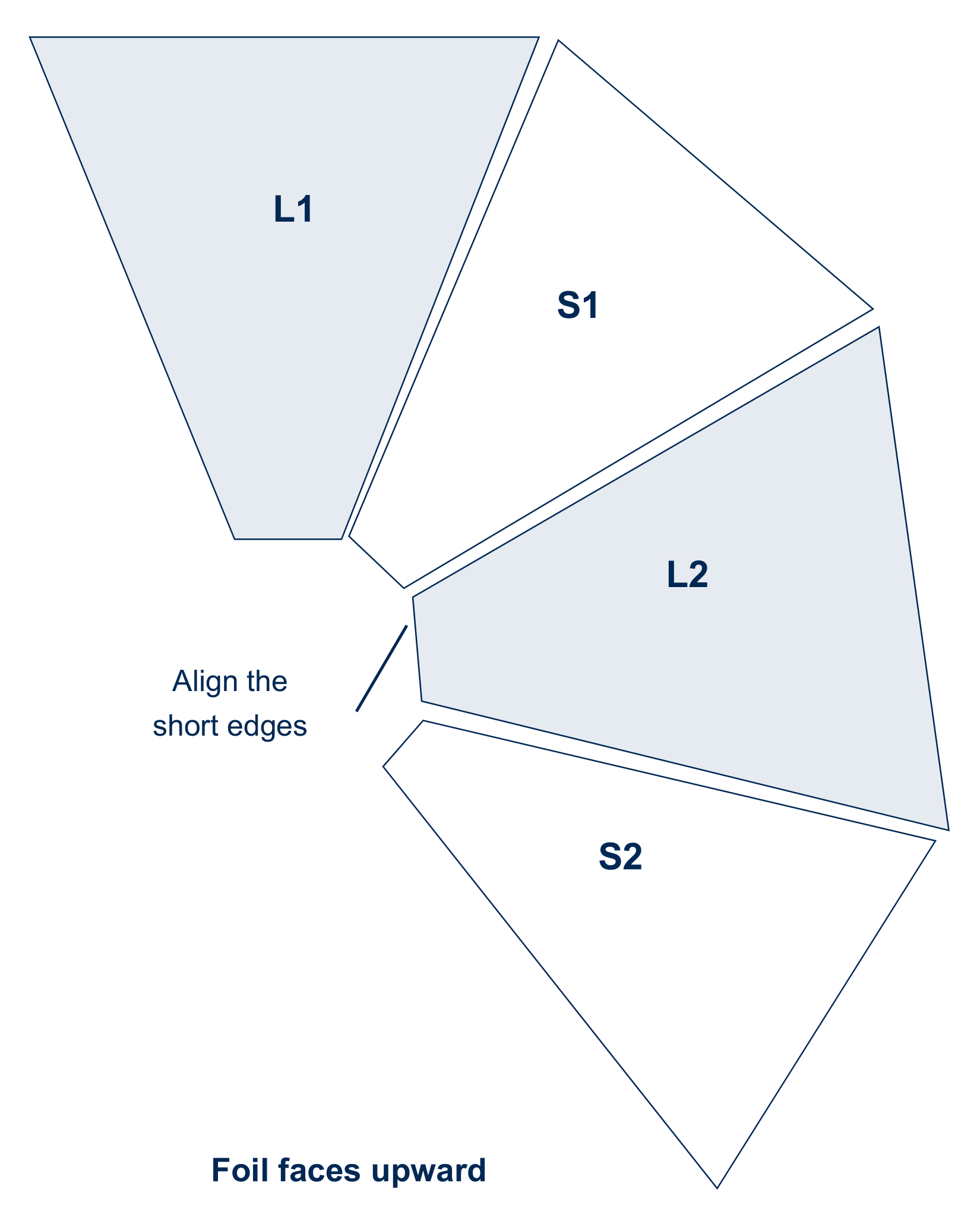
Figure 4. Alternate large and small panels, then tape the adjoining edges.
Prepare the can receiver
- Remove the bottom of the can with a smooth-edge can opener.
- Solder the 5.25 cm copper probe to the SMA feedthrough pin.
- Mark the midpoint of the can side, 5.25 cm from the capped end. Drill a 1/4-inch hole at this point.
- Place a wood block inside the can while drilling to prevent the wall from bending. Remove the block afterward.
- Solder the SMA feedthrough to the can with the copper probe extending inside. Keep the probe clear of the metal wall.
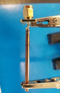
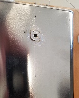
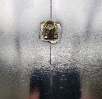
Figure 5. Probe, drilled can, and attached feedthrough, in order.
The photos show the connector outside the can and the probe extending into the receiver.
Attach the can to the horn
- Bend each 2 × 6-inch flashing piece into a squared S shape. The pieces support the joint between the can and horn.
- Place the horn upside down. Tape the flashing pieces to the horn, as shown in the first photograph in Figure 6.
- Align the open can with the horn opening. Keep the flashing outside the can.
- Fit the flashing around the joint. Secure it to the can with duct tape or foil tape.
- Cover the inside seams with foil tape. Close all gaps between the horn and can.
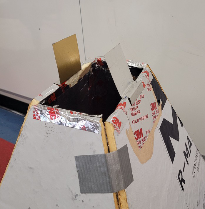
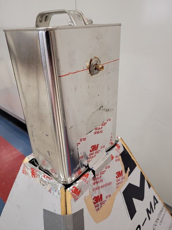
Figure 6. Flashing before and after attaching the can.
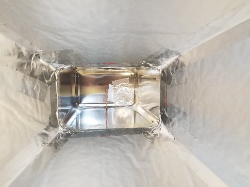
Figure 7. Interior seams fully covered with foil tape.
Next, build the cradle and stand to support the completed antenna.
Other Horn Designs
Baby DSPIRA Horn is a smaller design with its own stand. It uses the same components and software as the standard horn. Use the mini-horn construction guide (view PDF) and the demonstration videos below.