
First: Order the Components of the LNA
- View the parts ordering guide (view PDF). It lists the components and suppliers.
- Order a bottle of silicone conformal coating. Coat the circuit board after soldering all components. The coating is not an electronic component of the LNA. This coating will protect your LNA from moisture, corrosion, fungus, dirt, dust, thermal shock, short circuits, and static discharge. This product is available through Amazon. You can also do a Google search for silicone conformal coating to find other sellers.
Second: Assemble a Soldering Station
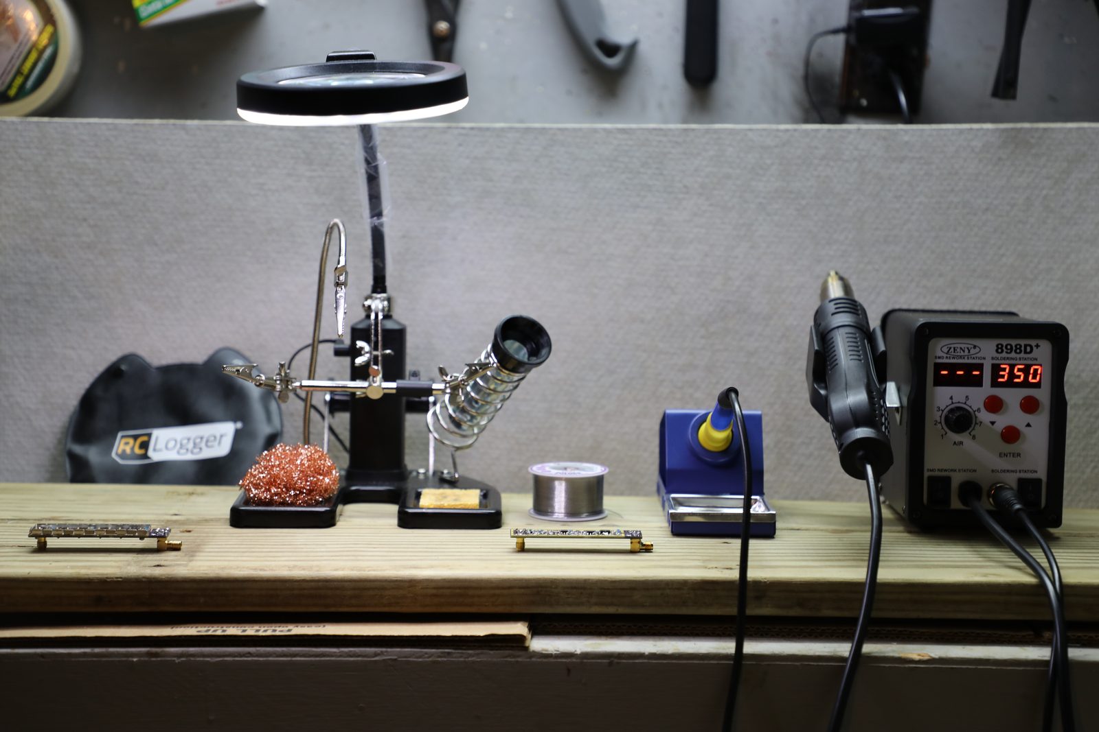
- Get a soldering iron and a hot air gun that have temperature controls. The cheap hobby soldering iron will not do. You should set the operating temperature of the soldering iron and hot air gun to 350°C.
- Get a soldering stand. Include a magnifying glass, light, movable helping hands, cleaning sponge, fine-tip tweezers, and cleaning mesh.
- Get a spool of solder. Most solders are a mixture of tin and lead. Tin-and-silver solders are also available. They melt at higher temperatures and are much harder to use. Solder also comes in different thicknesses or diameters. A thickness of 0.025 inches is a good size for the soldering you’ll be doing.
- The following is a picture of a typical soldering station. It is also called a rework station. The setup shown was purchased from Amazon for about $100. You can also go online and search for soldering irons, hot air guns, rework stations, and soldering stations.
Third: Solder the Components onto the Circuit Board
- There is no best order for soldering the components onto the circuit board. If you are new to soldering, complete all components of one type before moving to the next. Beginners typically solder components in this order: capacitors, resistors, inductors, transistors, ICs, SMA connectors, and the cover. Capacitors and resistors are easiest to solder onto the board. Start with them to practice the techniques.
- Experienced builders can start with the hardest components. Try this order: transistors, ICs, inductors, resistors, capacitors, SMA connectors, and the cover.
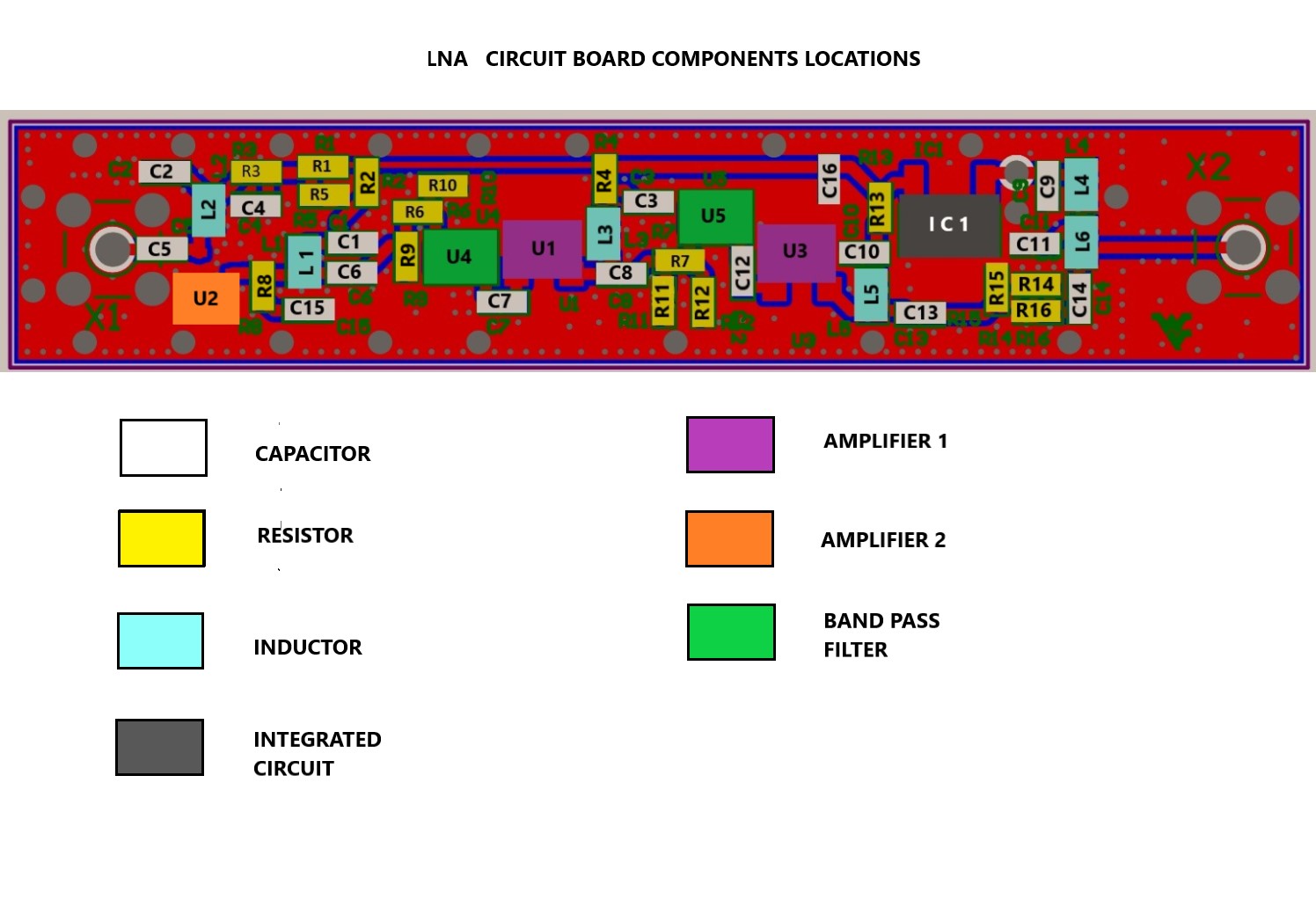
- The following is an easy to read diagram of the circuit board. Each type of component is color coded and labelled. The orientation of each component is also indicated (vertical or horizontal).
Detailed Soldering Instructions for Each Component
Soldering a Capacitor
Touch the soldering iron’s tip to a pad. Melt a small drop of solder onto it. The drop should barely fill the pad. Place one end of the capacitor onto the drop of solder. Touch the iron’s tip to both the capacitor’s end and the solder drop. The heat melts the solder, which should pull the capacitor toward the pad. This should make a good connection between the capacitor and pad. Solder the capacitor’s other end to the second pad. Touch the iron’s tip to both the pad and the capacitor’s end. Touch the solder to the end of the capacitor and soldering iron. A drop of solder should melt and adhere to the pad and the end of the capacitor. Watch the video below for a demonstration of soldering a capacitor.
Soldering a Resistor
Soldering a resistor is identical to soldering a capacitor. You may encounter difficulty in getting solder to melt on the pad. That pad is part of the ground. The ground is copper that extends around the circuit board. You must heat a large portion of the board before that pad reaches the correct temperature. Watch the video below for a demonstration of soldering a resistor.
Soldering an Inductor
Begin soldering an inductor as you would other components. Melt a small drop of solder onto a pad. An inductor’s metal plate is underneath it. This makes soldering harder than with resistors or capacitors, whose contacts are on their sides. It is important to have the tip of the soldering iron touching the bottom plate of the inductor. It is also important to leave as much room as possible on the other pad. The pad will be soldered to the thin side of the bottom plate of the inductor. Watch the video below for a demonstration of soldering an inductor.
Soldering a Transistor
There are three different types of transistors to be soldered onto the circuit board. Each one has its own difficulties in soldering onto the circuit board. You should watch each of the following videos before soldering to determine the orientation of each transistor.
Transistors U1 and U3
Transistor U2
Transistors U4 and U5
Soldering an Integrated Circuit (IC)
Soldering an IC is similar to soldering transistors U1 and U3. Watch the video below for a demonstration of soldering an IC.
Soldering the SMA Connectors
There are two SMA connectors on the circuit board: X1 and X2. One SMA connects the antenna feed to the LNA (X1). The other connects the LNA output to the AirSpy (X2). Watch the video below for a demonstration of soldering an SMA connector.
Soldering on the Protective Cover/RF Shield
The protective cover should not be soldered on until after the LNA is tested and is determined to function properly. Once the protective cover is soldered on, it will be difficult to make any repairs. The protective cover is also hard to remove after it has been soldered on. Watch the video below for a demonstration of soldering on the protective cover.
Applying the Protective Coating
Applying the silicone conformal coating is the last step for constructing the LNA. Watch the video below for a demonstration of how to cover the LNA with the silicone conformal coating.